
From my readings, it appears that power distribution is one thing many people struggle to comprehend. There is a fair bit of (basic) mathematics involved, and it requires a certain degree of planning to get right. That said, there are people that will say “XXXXX is the right way to do it”; purely based on their own experiences; and they do not take into account the factors related to a specific installation.
LEDs, individually, do not use that much power. Your typical red LED used as an indicator on your TV, for example, uses around 20mA of current to illuminate, with a turn-on voltage of around 2.1V. This means it’s using about 0.04W of power. This is tiny in the grand scheme of things for a TV, which can draw in excess of 100W.
When talking about RGB LEDs, internally, these have 3 modules, one for red, green and blue. By varying the current through these, we can mix many millions of combinations of colours. These use similar currents, around 20mA per LED segment, or 60mA if they were all turned on together (at full white). The driver chip may limit this, however. The WS2811 chip has a driving current of 18.5mA per colour, so 55.5mA for all three segments.
Now, imagine we have 1,000 LEDs. This means we need 1,000 * 55mA = 55 amps of current! At 5V, this would be 275 watts, and at 12V this would be 660 watts. Extrapolating to my expected LED counts of 5,500, that would be a total of 302.5A, or 1,512.5W at 5V or 3,630W at 12V. The latter is the size of my hot water system element!
So why is it higher consumption at 12V than 5V?
Ohms law would state that at a given resistance, the current would be lower if the voltage would be higher. Yes, that’s absolutely true, except that LEDs are not linear. They must be fed by a constant, limited current source. So no matter the input voltage, they will always use the same amount of current. There is a voltage regulator or resistor in 12V pixels, which act as a dropper and dissipate the remaining power. Which essentially means that for my installation, I would be dropping just over 2100W as heat, at full brightness, on full white. Not very efficient at 12V. (Note: Strip LEDs work slightly differently to bullets, and are more efficient, but that’s another story). That’s a typical bar heater!
Now – before someone corrects me, yes, I am aware of LED drivers that work differently at a much lower current; which significantly drop the power requirements for 12V (GS8208, I’m looking at you) – the discussion below is all based on a standard WS2811 driver chip.
Which then begs the question, why would you want to use 12V at all?
It comes down to ohms law, in relation to the cabling. An ideal wire is a dead short, it has zero resistance, and can conduct infinite current. Unfortunately, we are not blessed with theoretical components, but we must live in the real world where we have certain physical limitations.
Wire comes in different diameters, which is measured by its cross-sectional area, in millimetres squared. Alternatively, the Americans love to use some weird and mathematically useless unit, called American Wire Gauge, or AWG for short.
Now I’m going to get a little maths nerdy here, and there are some certain assumptions/constants about the setup that we’re going to use, to simplify the maths.
- The cable from the power supply to the LED string is 15 metres.
- On the LED string, we have 600 LED nodes, which at full white, will draw 33 amps
Let’s take typical mains cable that you’d find in the walls of your house. This is usually 2.5mm^2 cable. If it’s made from copper, it has an effective resistance of around 6.9 ohms per kilometre, or 0.0069 ohms per metre. So because we now have our length, resistance, and current we can calculate the voltage drop, using ohms law of V=IR.
Let’s start by working out the total resistance.
Resistance = Length * 2 * Ohms/metreWhy times two? Because our current goes from the power supply, up the length of cable, through the LEDs, and back down the cable to the power supply, so in effect, we have two times the “twin” length of cable to consider.
Voltage Drop = Current * (Length * 2 * Ohms/metre)
Voltage Drop = 33 * 15 * 2 * 0.0069
Voltage Drop = 6.831 Volts!
So if we had a 5V power supply, we wouldn’t have any voltage left at the end of the string. If we had a 12V power supply, we’d have 5.169V at the end. The LEDs might just light, but not quite.
As you can see, the drop is linear, and not dependent on the incoming voltage or the voltage of the LEDs. So if we have more volts in and one end, we’ll have more volts out at the other, at the same current.
Let’s reverse the equation. Let’s work out the resistance of cable I need to have a 10% voltage loss on this length of cable, and from there we can find out the size of cable needed.
Ohms Per Metre = Voltage Drop / (Current * Length * 2)

At 12V
	Ohms Per Metre = 1.2 / (33 * 15 * 2)
	Ohms Per Metre = 0.00121 ohms

At 5V
	Ohms Per Metre = 0.5 / (33 * 15 * 2)
	Ohms Per Metre = 0.0005051 ohms
And that would equate to the following size wires- based on a table I found online.
12V = Approx. 16mm^2 cable = 4.5mm Diameter
 5V = Approx. 35mm^2 cable = 6.7mm Diameter
Those are both MASSIVE cables, and not something you want running around your yard. Basically the takeaway from this is that you do not want to push 33 amps over 15metres for a 10% voltage drop.
So how do you reduce the size of the cable? Or is there a better way to do it?
Yes!
- Reduce the length of the cable. Based on the above calculation, we can see that the voltage drop is directly proportional to the length of the cable. Halve the length, halve the drop.
- Reduce the current running through the cable. Again, it’s directly proportional. Halve the current, halve the voltage drop.
- Why not do both?
To satisfy the first, we could move the power supply closer to the LEDs. And to satisfy the second, we could drop the number of LEDs on a cable from the power supply. Rather than one big thick cable, we could spider out multiple smaller cables from the power supply.
More maths
Let’s say we put the power supply closer, and we can reduce the length to 3 metres. Let’s also split it up, so we have 200 LEDs on each power cable. We’re going to assume we’re using the same size cable (2.5mm^2 copper).
This then gives us the following formula:
Current = 0.055A per LED * 200 LEDs = 11A total current
Voltage Drop = Current * (Length * 2 * Ohms/metre)
Voltage Drop = 11 * 3 * 2 * 0.0069
Voltage Drop = 0.4554 Volts
At 5V, this leaves us with 4.5446V (9.1% drop), and at 12V leaves us with 11.5446V (4.5% drop).
Much better. 15 times less voltage drop. We can run a show with this!
Keep in mind, as well, this is on full white, all LEDs, at 100% brightness. If you were to run a show like that, you’d blind your neighbours and no colour is no fun! So not realistic. However; you could theoretically turn on all lights like this.
It would mean we need 3 cable runs to drive our 600 LEDs, rather than one, and we’d need to position our power supply correctly. Good practice to do it this way.
Now – I’ll point out that there are a bunch of other things that are not quite accurate to the practicality of it which are not considered in the above calculations. One such example is that it does not take into account that the LEDs are mounted on (cheap thin) wire themselves, which also have their own resistance.
This brings us onto the next discussion point – power injection.
LEDs come on wire which, to be perfectly frank, is inadequate. You can order it with 20AWG or 18AWG cable, but that’s only what’s printed on the side. I prefer to refer to what you purchase with LEDs as CWG – Chinese Wire Gauge. My ‘off-the-cuff’ conversion is AWG = CWG + 4 – so if you see it advertised as 18 gauge, it’s probably closer to 22 gauge (thinner).
So with the currents involved, the further you are away from the power supply, the more voltage drop there is. This could mean that the first LED is getting 100% of the voltage, and by the end of the string, there’s only 50% of the original voltage left. This causes the LEDs to go yellow / orange / red colour, as the Blue and Green LEDs will switch off first.
Power injection is connecting power at each end of a string of LEDs, and sometimes in the middle, with a much thicker cable.
Here are a few different images that I’ve pinched (from https://www.doityourselfchristmas.com/) that show the methodology.
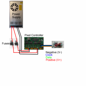
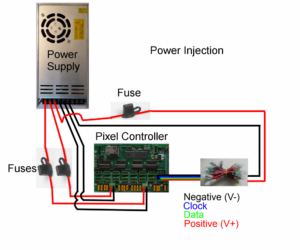
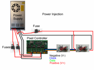
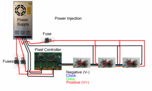
By running the thicker cable as the injection point, you overcome the resistance of the wire on the pixel string, thereby reducing the voltage drop. This then means the pixels get a more even voltage, and the colour reproduction is more precise.
Putting it all together
So with all this in mind, how am I planning to power my setup?
I’m going to be doing a combination of things.
- To keep things effficient and not let power go to waste, I plan to use 5 volt pixels all round.
- I plan to keep the 5V power supplies close to the props
- I plan to power inject every 50-100 pixels, to ensure the pixels all receive decent power.
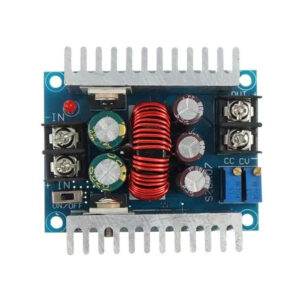
- To satisfy 1) and 2) without running mains wiring everywhere, I plan to use 24V distribution and do at-prop power conversion.
What ho? 24V?
What is this last bit all about? 24V? No one said anything about that. All the talk above is about 5V and 12V!
Thinking back to our power calculations above, we can reduce voltage drop by reducing current. Now, whilst 12V pixels are not able to do this due to their design, by implementing DC to DC converters, we can.
Power = Voltage * Current
Power is consistent across a DC to DC converter (ideally, assuming 100% efficiency).
So mathematically, Power In = Power Out; refactoring and solving for Current Input:
Voltage In x Current In = Voltage Out x Current Out
Current In = (Voltage Out x Current Out) / Voltage In
With 5V pixels and 24V supply, this means that
Current In = 5/24 * Current Out
Current In = 0.208 * Current Out
o we’re straight away reducing our current requirements by 80%. This means the voltage drop on the feeder wires is 20% of what’s required at the props.
This is exactly why the power companies give you 240V, but distribute at 11kV, 33kV and 330kV. The current requirements are much lower at high voltage, and so thinner cable can be used (or more end-users for the same size cable).
Coming back to our 600 pixel example above, with 15 metres of 2.5mm^2 cable:
The current was 33A at 5V. Translate this to 24V gives us 6.875A. Let’s assume that we’re not completely efficient, and we lose 10% in the converter – so 7.6A to be on the conservative side
Voltage Drop = Current * (Length * 2 * Ohms/metre)
Voltage Drop = 7.6 * 15 * 2 * 0.0069
Voltage Drop = 1.5732 Volts = 6.55% total drop
This leaves us with 22.4268V at the far end. Heaps for the DC to DC convertor to work with!
The DC to DC convertors are also alot more tolerant of voltage drop. If they are set to put out 5V, they will keep doing so, as long as the incoming voltage is over 8V. In other words could lose 66% of the incoming voltage before they cut out. Note that this isn’t an excuse to just run super thin wire everywhere, it needs careful planning too, but it does end up being a cost saving in the wire, as well as being easier to work with.
I’ve yet to draw up the full diagram, but so far all the calculations for this method of working means that I will be running pretty efficiently, and will be able to light up to any setting I wish, without fear my power requirements aren’t up to scratch.
Once I get everything designed, I’ll put together another post detailing all the connections, wire lengths, measured resistances, voltage drop measurements (real life vs theoretical) etc.