So it’s been a little neglected here in the website world. I just cleared out close to 4,500 spam comments awaiting approval! Thank you Russian scammers for filling it up.
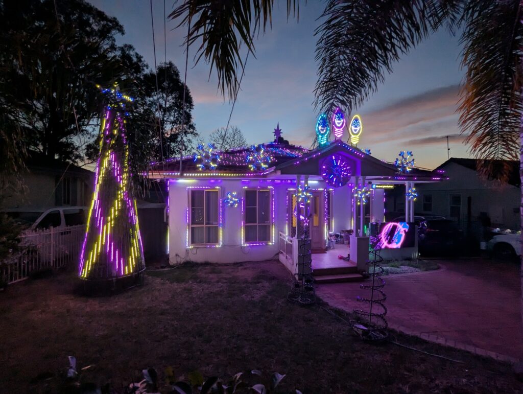
This year the megatree got a huge upgrade. It has gone from 1,500 nodes (20 strips of 75 nodes per strip, at 2 inch spacing) to 4,500 nodes!! (30 strips of 150 nodes per strip, at 1 inch spacing) – The extra density has made a massive difference and it looks stunning. Part of this required a controller box rebuild, to support 12V pixels.
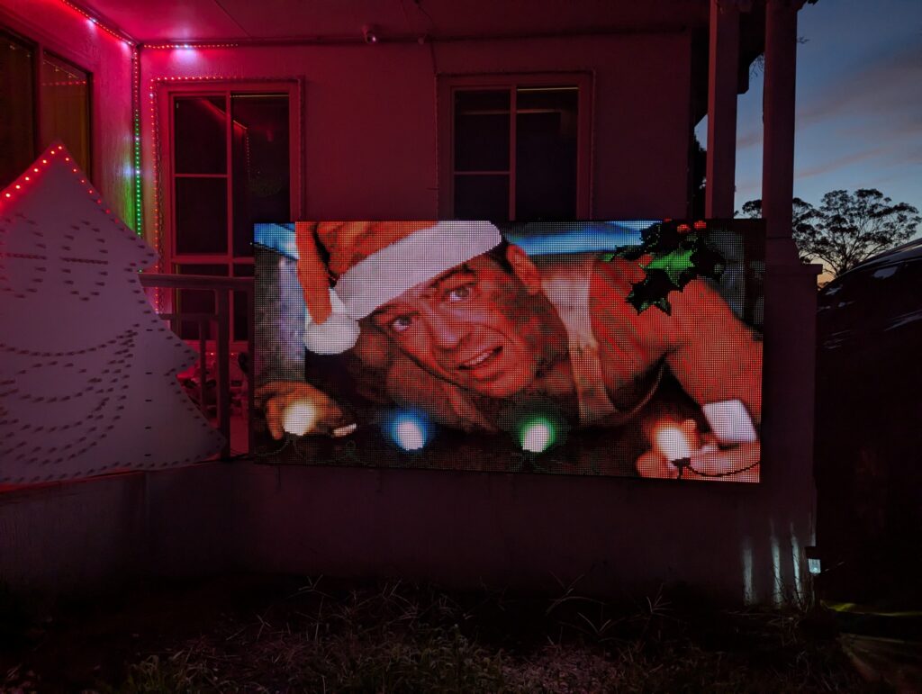
Additionally, another heavy hitter is the addition of a P6.67 panel matrix – totalling 288×144 resolution – 192cm by 96cm. This has brought some new sequences to life with effects, pictures and video. It is crazy bright, I am running it on 1/9 brightness setting so I don’t burn retinas in the evenings. More details on the build for this coming soon.
The third major addition is a high-density prop, in this case, a Showstopper Spinner. This was made from the 5V pixels that came out of the megatree post-upgrade. I am _really_ happy with this prop, it maps very nicely onto sequences, and gives some amazing effects. It taking a bit of “centre stage” in the porch gable gives it the attention it deserves.
Soon I’ll work on creating another behind-the-scenes video – there have been changes to the overall architecture of the the show; powering and push to listen.
So the big question being asked is: “What’s changing in 2023?”. And the answer is, physically, not much. I have been pretty happy with the initial layout, and found it ticked 90% of the boxes that I wanted to tick. A few minor adjustments are being made as below.
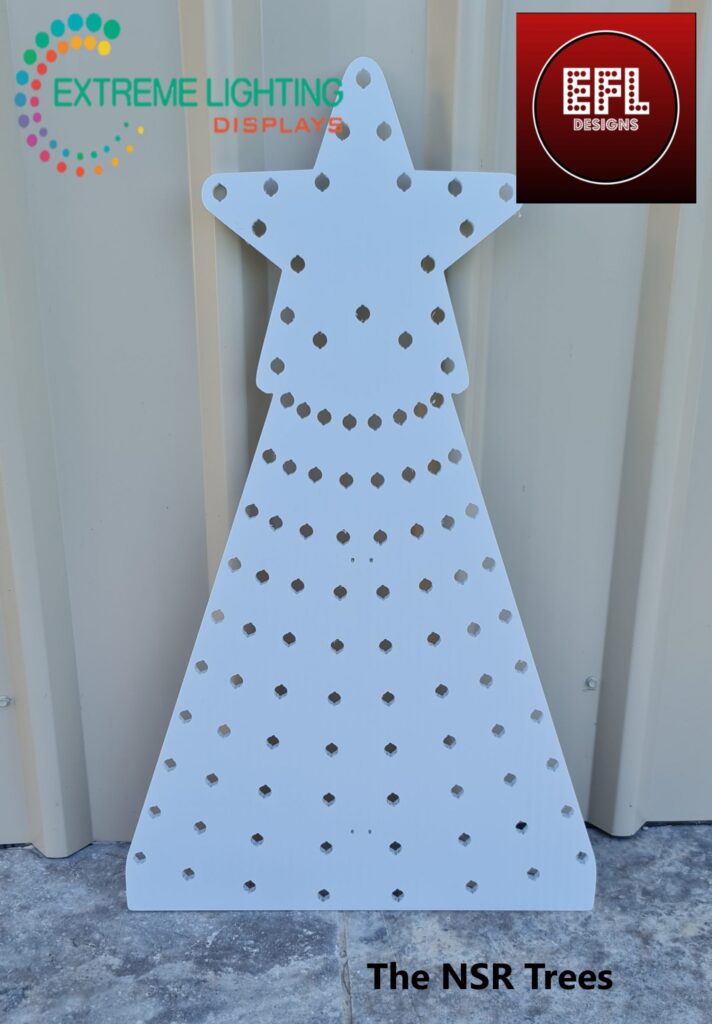
I have bought a few mini trees to go underneath the arches, and two more singing bulbs. These guys will make a trio and will live next to the singing tree. And finally, where the original bulb was on the roof, a fourth snowflake to match the other three.
The other change is the addition of a matrix array to the solar panels. I am still toying with ideas with how this might work; including using seed pixels.
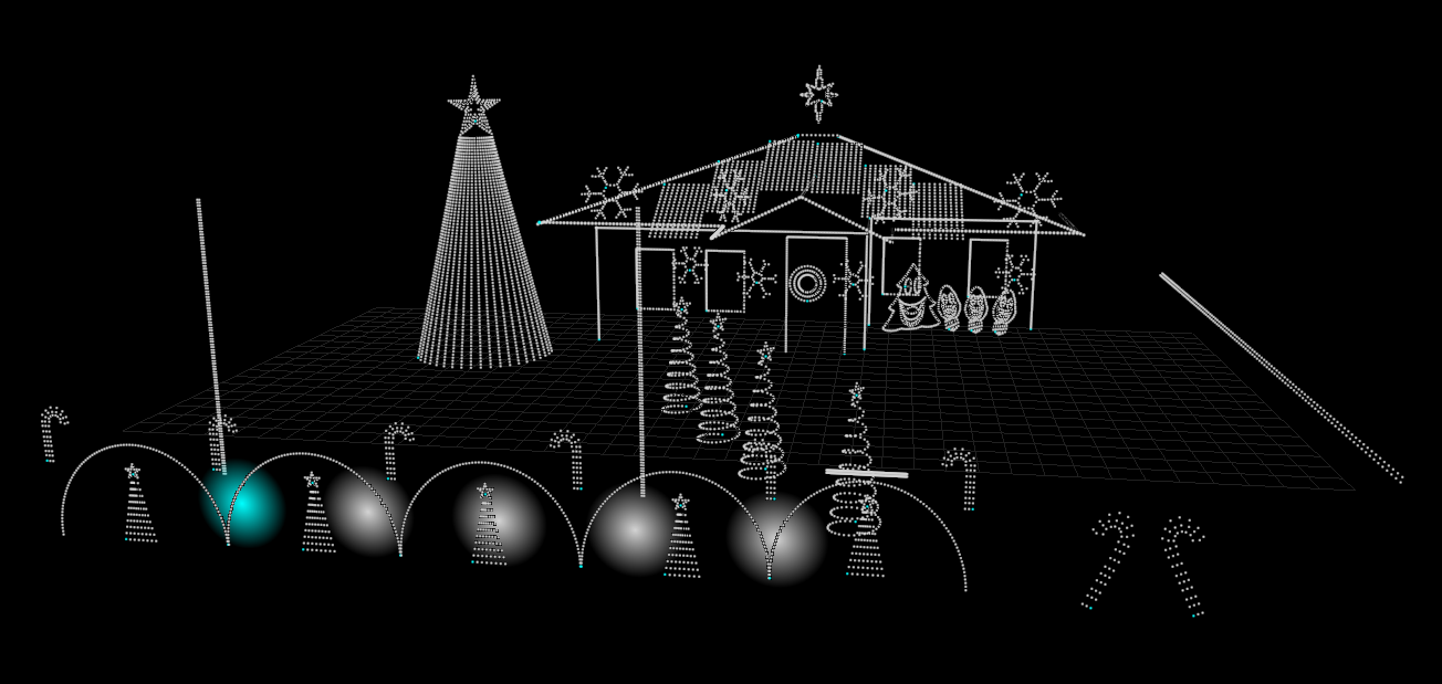
One other final change is moving the Bethlehem star from above the front entry way to be on top of the house. I think this will act more as a centre piece; and certainly will stand out a bit more. It was hidden behind the palm tree fronds last year, and didn’t create the impact I was hoping from it.
Here’s a quick sneak peek of what it may look like; from xLights.
I have also got a few more sequences on the way; these are professional ones which I have obtained through various means. It should really help the display pop and I’m looking forward to showcasing them in 2023.
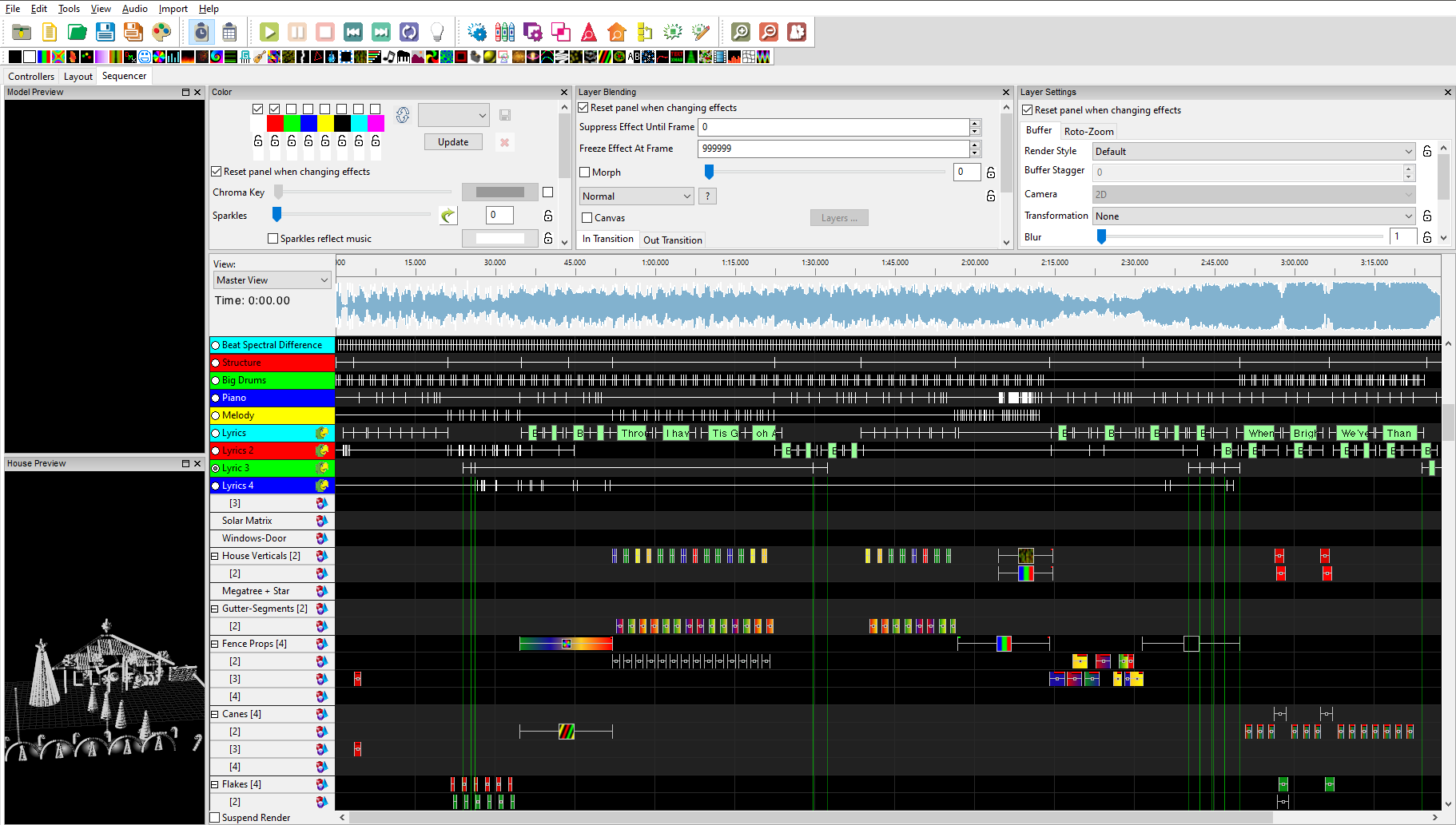
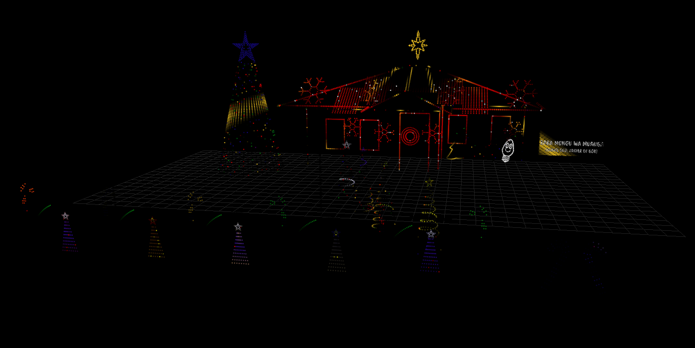
Another sneak peek of a sequence in progress, and a section of it’s output. WordPress seems to munge the images a bit unfortunately.
I have had a number of questions about how I went about making the roof lines and mounting them to tile.
Making the Roof Lines
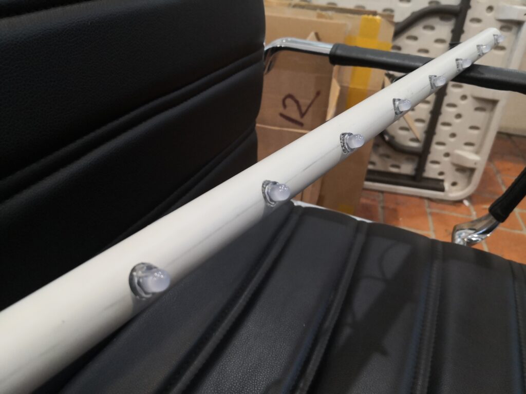
The short version: Lots of conduit. And lots of drilling.
The roof lines are 12mm front holes drilled at 3″ / 75mm spacing in 25mm conduit. On the back, a larger 18mm hole facilitates the insertion of the pixel.
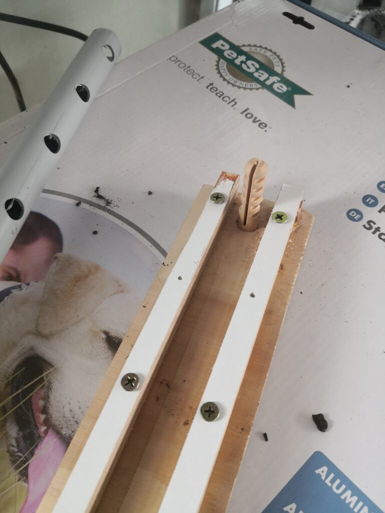
This was done by making a jig to hold the conduit without rotation, ensuring the lines were straight and not twisting around the conduit.
It was marked at the 75mm centres, and the first hole drilled through with a 12mm step bit, front and back. This was then inserted onto the jigs locating pin.
Finally a 3mm drill was used to pilot hole from the front, and out the back for each pixel position. These were then enlarged with a step bit to 12mm (front) and 18mm (back). All in all, lots of drilling.
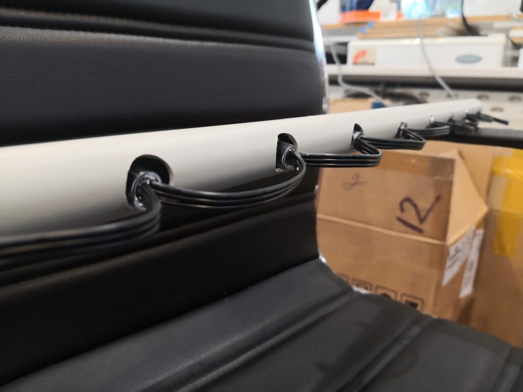
Mounting the Roof Lines
A picture is worth a thousand words. A video is worth even more.
When filming the display the other weekend, we managed to get some drone footage captured. Some of it was just “junk” footage, but in this particular instance is pretty handy to see how things are organised on the roof of the house.
This is completely unedited and dumped straight from the drone.
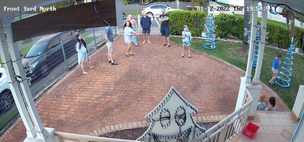
So 1st December was our first ever show. A 99% success. One issue to fix (the show stopped playing in the first song and went back to the out of hours display) and one minor change to make to the playlist.
Had a few neighbours pop by to say hello, as well as some friends and their kids.
Everyone seemed to enjoy it really well, loved the music and the flashing lights. Must say, some of the feedback was absolutely excellent and unexpected. Thank you!
Want to see what makes up the show? Here’s a 20 minute run through where I explain the components, the things that were put together, and how it all hooks up.
I’ve been very quiet on the blogging front, words have never been my forte. But, that’s not to say that progress hasn’t been made. Here’s a preview of what has been done so far. Just pictures and a small bit of text.
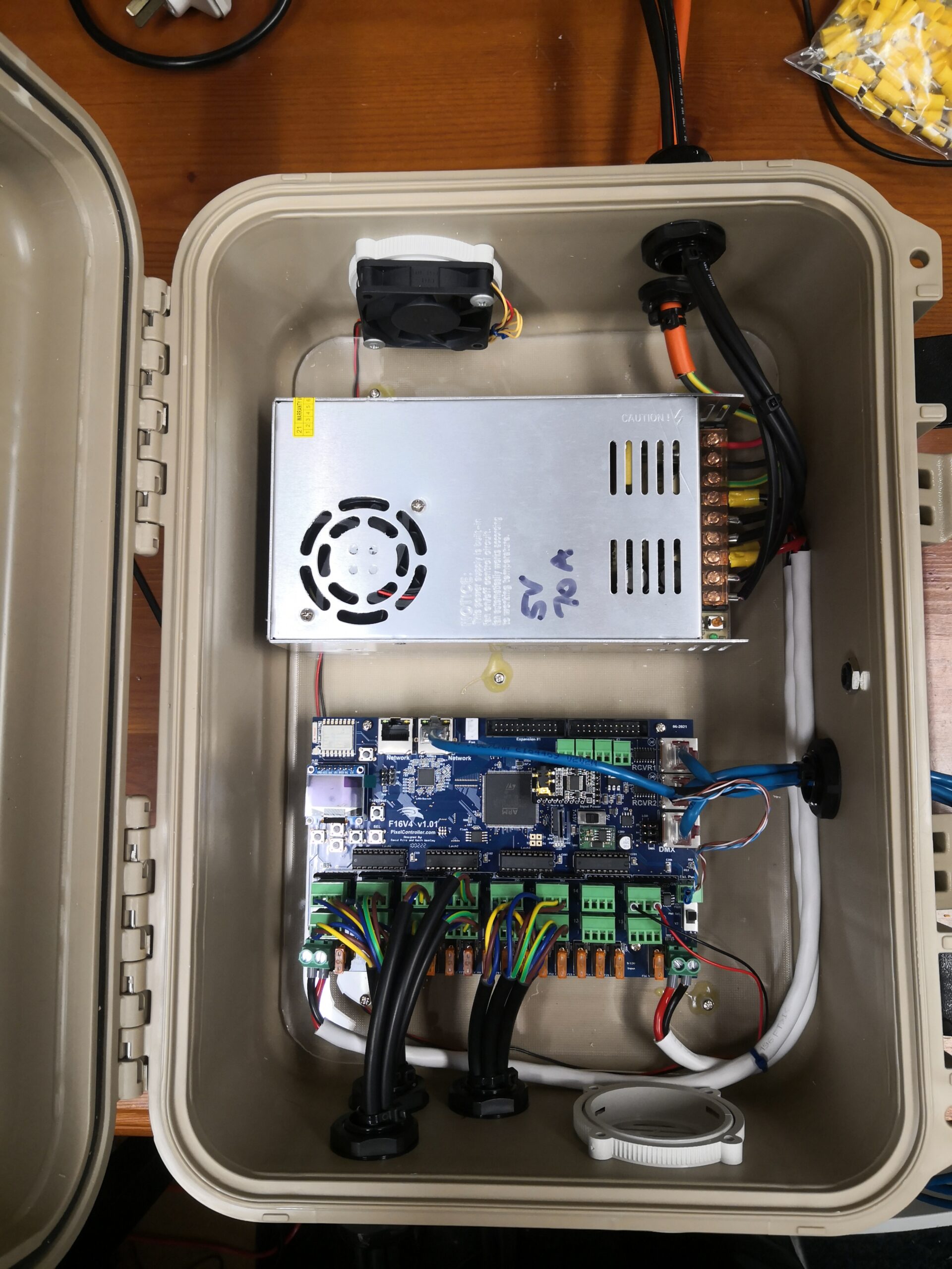
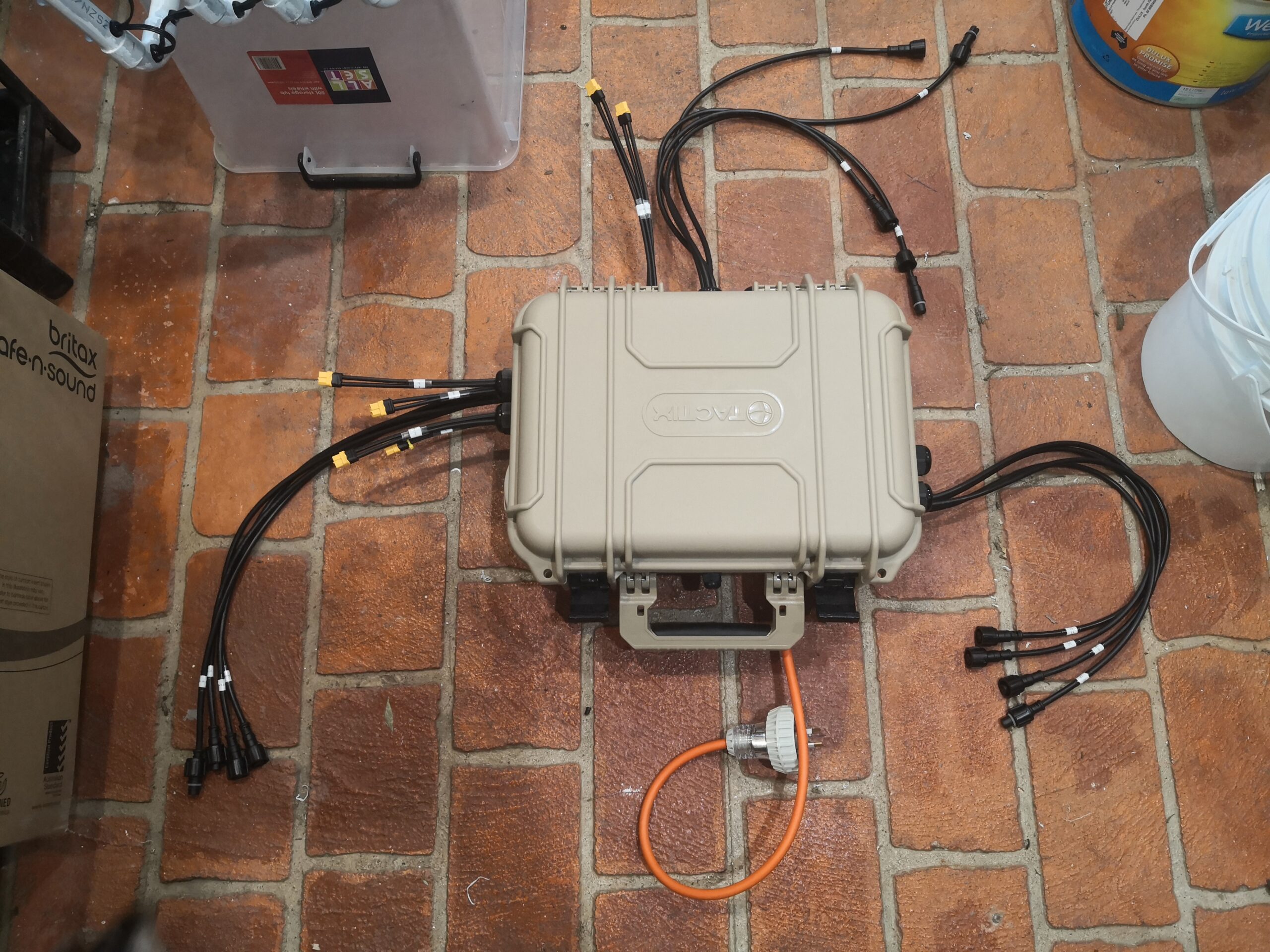
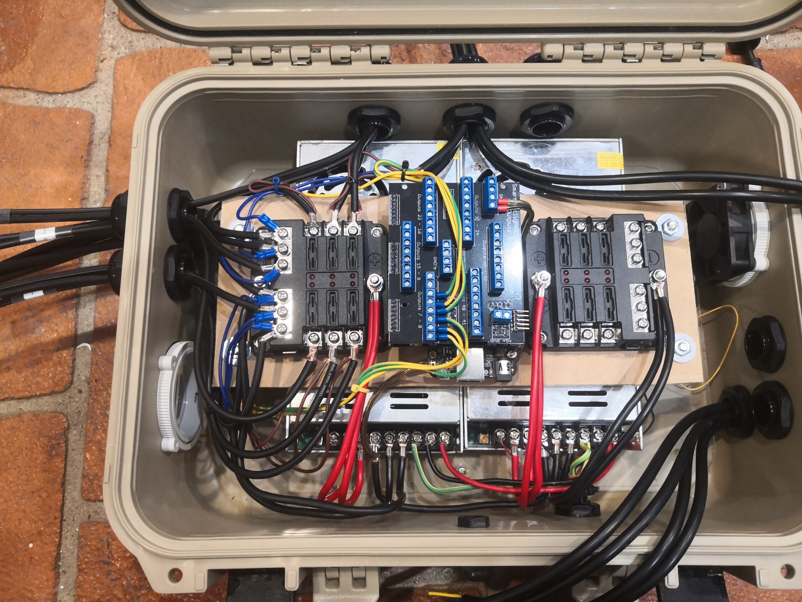
Some controllers have been built. Here are two – the Falcon F16V4, and the mega-tree PixelBone 48 (half built)
F16v4 with a 350W PSUMegatree Controller, closedHalf-wired MT controller. Right side is now complete
A bunch of pixels and pigtails were delivered
4000 pixels, 1500 strip LEDs and a heap of cabling!
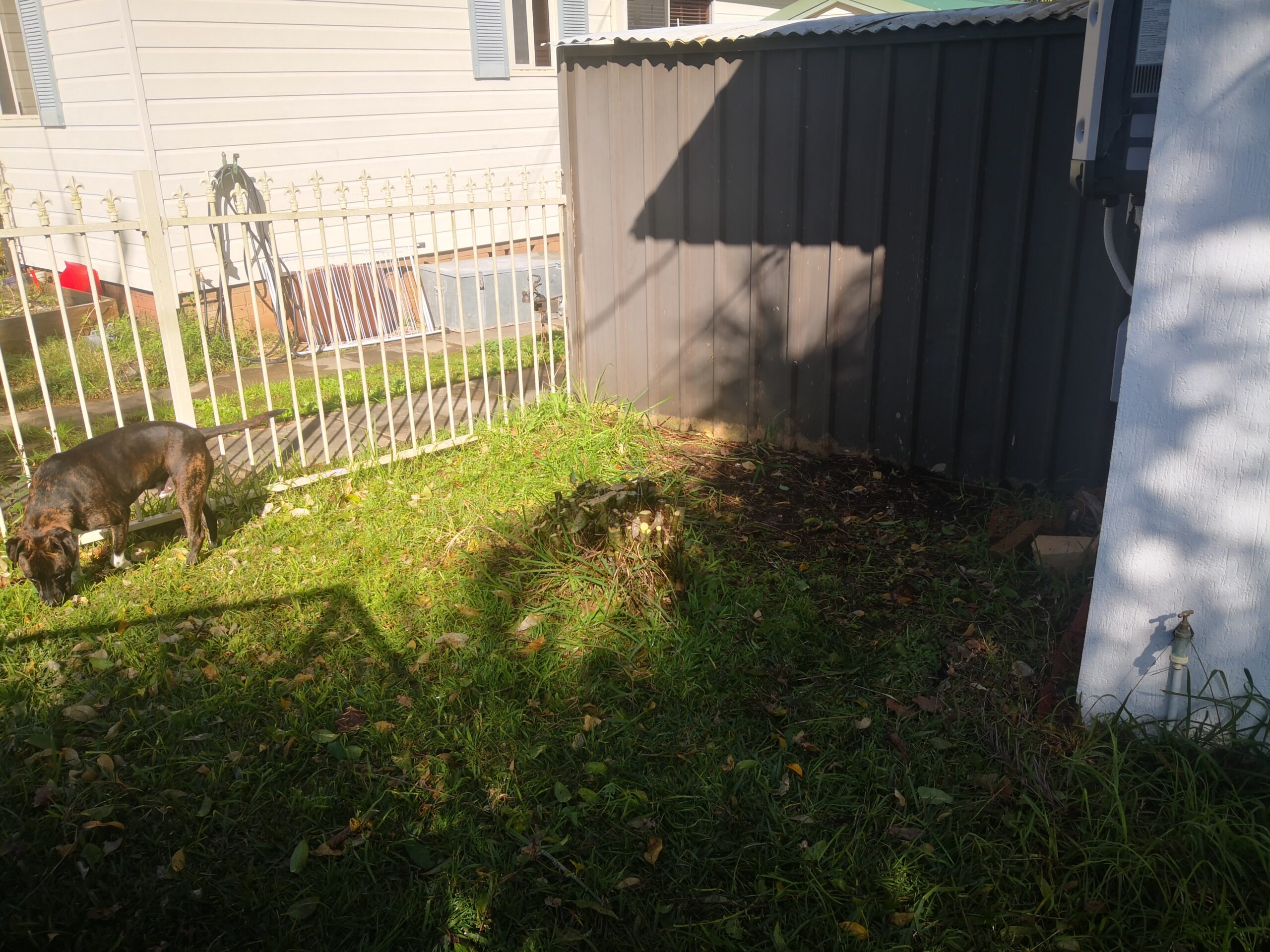
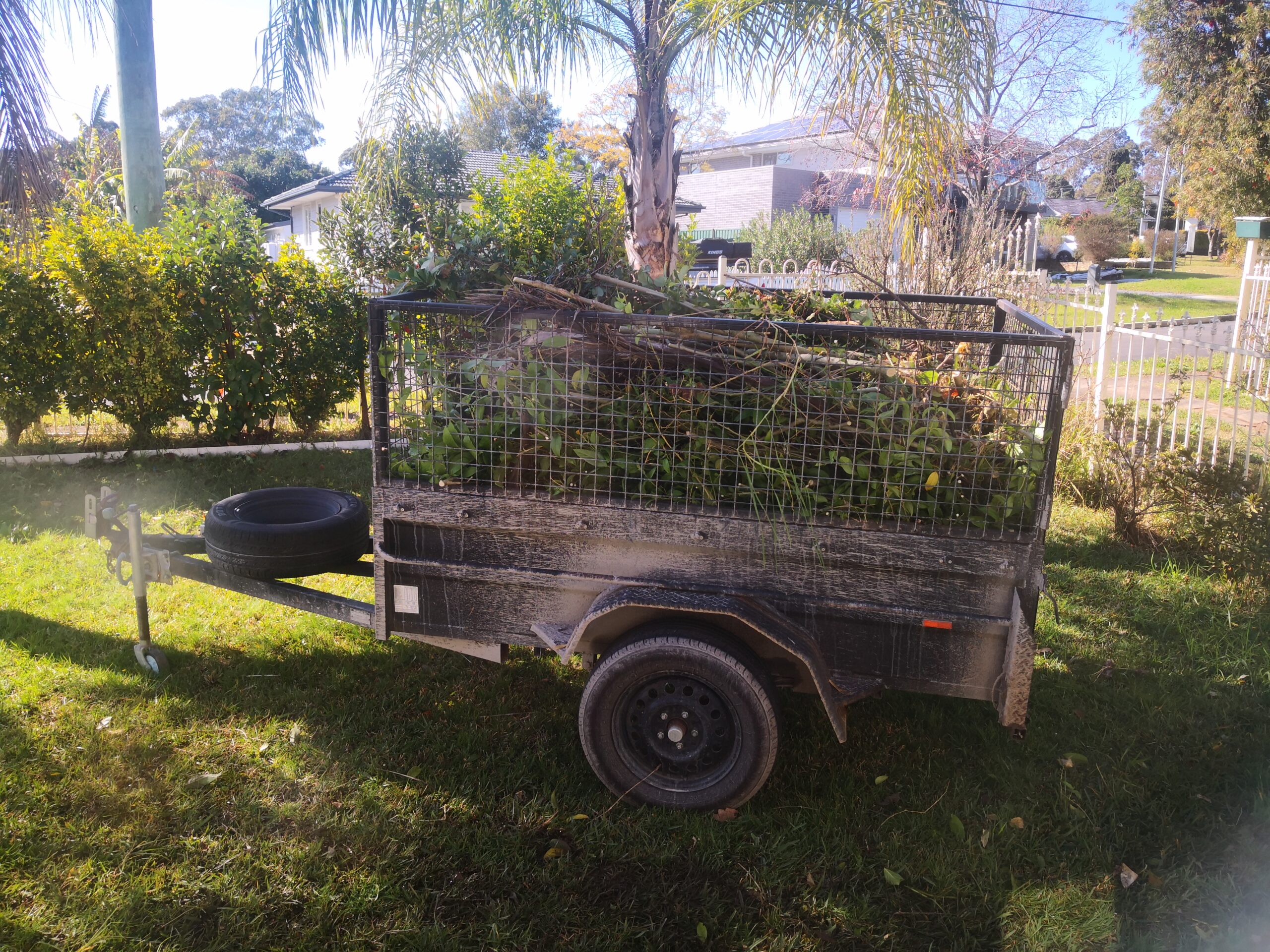
There was also some serious gardening done, including removing a bush
Where the bush used to be. Hello Mega-Tree space!Ready for green-waste disposal
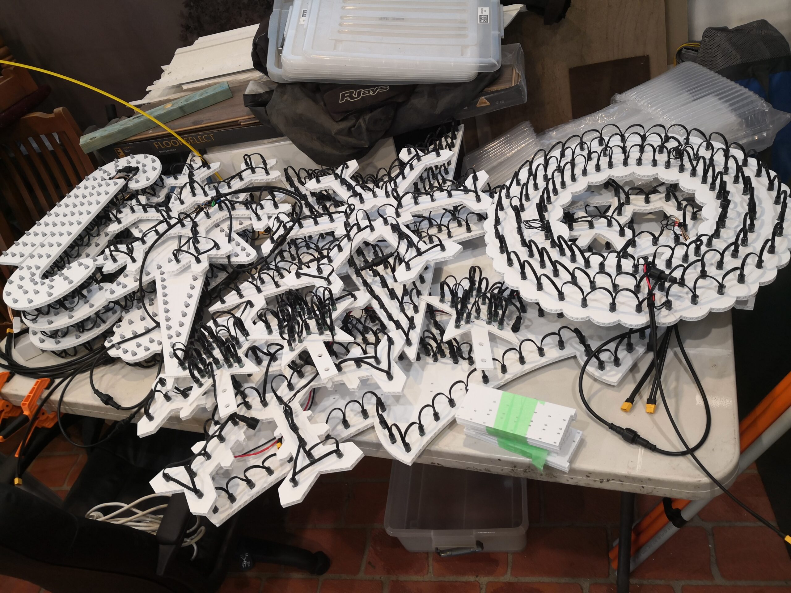
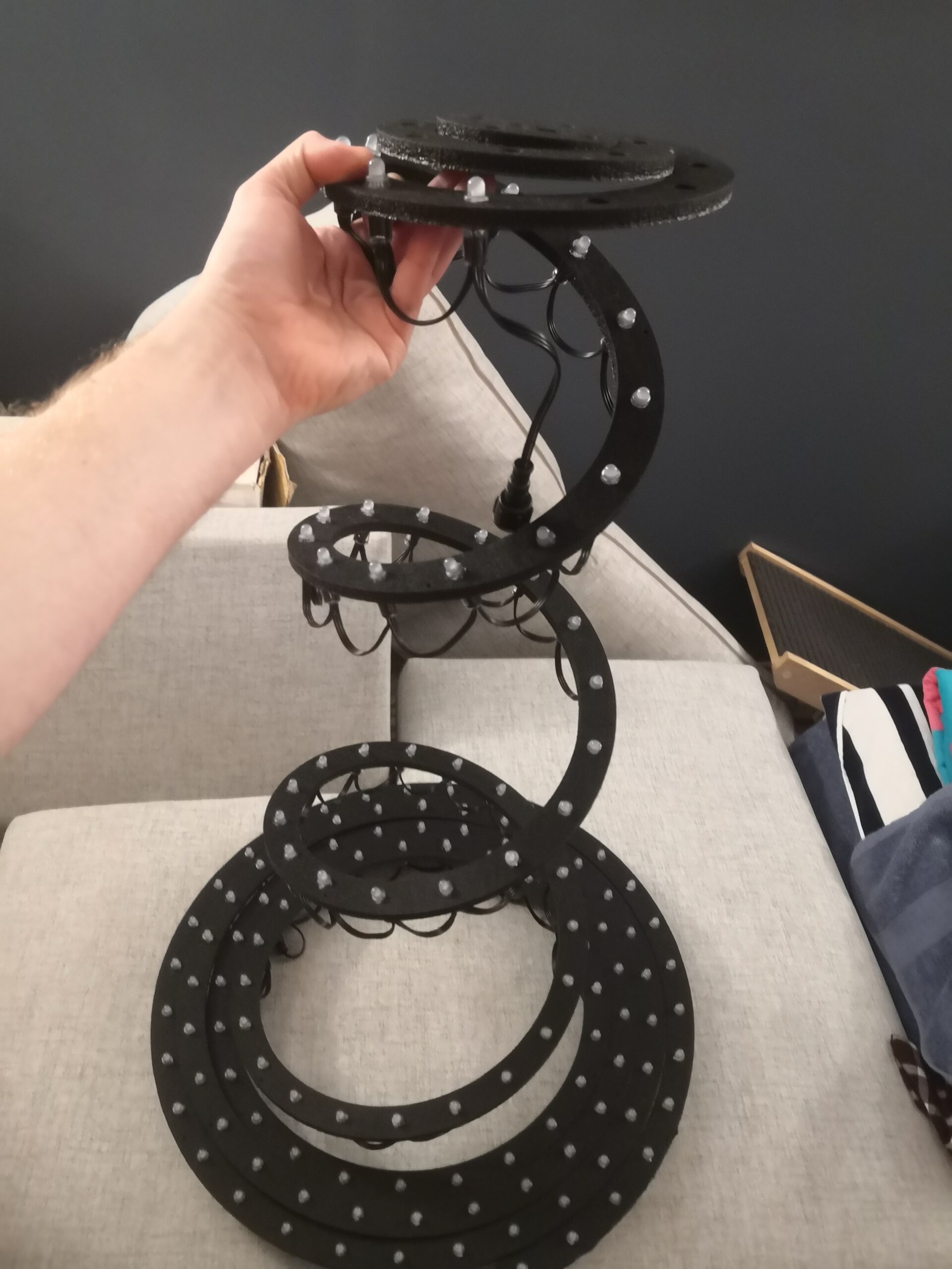
Pixels were pushed into props, house outlines started to be drilled, and spiral trees experimented with
PIxels pushed into coro propsHouse outlines drilled out of conduitSpiral tree made from plastic foam
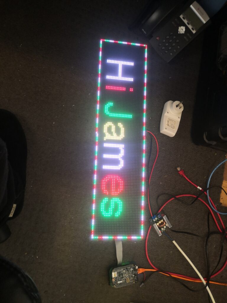
Experimented with some P5 panels to use as a tune-to sign.
P5 Panel in testing
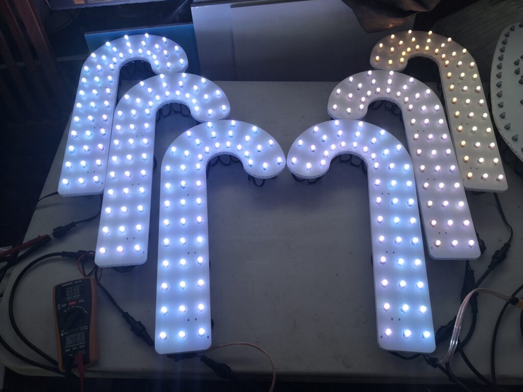
Also saw the effects of voltage drop
Look at that colour change, left to right. Very noticeable.
This is not just one decision. There have been days and weeks thinking about all these intricacies. I note that whilst I am writing this blog as I make decisions, I am describing many things that have occurred over the last two months. My discussion on hardware below will reveal that not only have I worked out what I want, I have also procured many items, and started configuring them and getting things working, so it all is ready to go. It’ll also show that many choices are fluid, and have to change as I encounter issues, or decide that there’s a better way of doing things.
Hardware can be broken down into many components, which I will discuss in turn.
Controllers
Show Runners / Playback
Pixels & Props
Power Supplies
Cabling & Connectors
Mounting Hardware
Controllers
Right now, these are the hardest items to source. The reason being is that in 2022 the world is facing a significant component shortage, meaning integrated circuits for phones, cars, misc other electronics, and by extension, pixel controllers, are high in cost, and have immense backorder times (some in excess of 12 months).
As discussed in a previous post there are a few major players. Falcon is seeing stock selling out within 9 hours of release, and people begging for hardware on Facebook. Advatek have lifted their prices to deter sales and counter the higher prices – their PixLite 16 Mk2 has increased from $399 AUD to $599 AUD in the space of 6 months. The ETA on Kulp controllers is mid-May. Raspberry Pi’s are impossible to get and have gone from $59 to $199, and a Falcon controller is going second hand on eBay (with 4 days remaining as at writing) already at $460 USD ($613 AUD – they were $220 USD new!) So, I decided to look for alternatives.
These both plug onto a BeagleBone Black (or Green) board, and are relatively inexpensive – $120 AUD for the HE123, and $50 AUD for the PixelBone, and both requiring an additional $90ea for the BeagleBones. So for the three controllers, it’s worked out similar price to just one of the above mentioned controllers.
So what do these controllers entail which make them ‘more difficult’ to work with, and why are the cheaper? Most of that comes down to the fact they are not ‘hardware’ based, but ‘software’ based. Meaning that you need to load on Falcon Player to the BeagleBone and then configure it. There are also some other issues to contend with:
The EEPROM on the HE123 is not programmed, so FPP doesn’t know how to work with it out of the box. The PixelBone doesn’t have an EEPROM.
xLights configuration for ‘automatic configuration’ does not always work, and may need manual configuration
The PixelBone requires construction (I could get it pre-made, but where’s the fun in that?)
Not nearly as many people use them, so community support is much lower, and you’re on your own more.
I’ve always been technical, so these challenges sound interesting, and for the cost savings, it’s something worth tackling. One of my work colleagues had knocked up a EEPROM file for the HE123, which I’ve modified as there were some errors – testing has shown that this overcomes the first two issues. I’ve ordered an EEPROM to connect into the PixelBone board, and will also get an EEPROM file written to work with that too. These files and designs I have planned to share back with the original designers of the board so they can incorporate them for new customers.
One of the HE123mk2’s will also have a long range expansion board and a couple of receivers, so that I can run props further from the controller. This changes the signal from a standard single-ended ground referenced one, to a balanced/differential signal, which allows the signal to run many hundreds of metres without degradation.
All up, the three controllers I’ve decided to use will be split up between the Yard props, the House props, and the Mega Tree. There is enough capacity across them that should one die, I can run the show off the remaining two. (In fact, I could probably run off one from a capacity perspective, but there are other limitations – such as cabling).
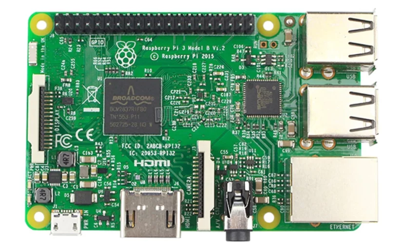
As well as the pixel controllers, I am also running the Hanson DMX2-24 board, as previously discussed, which will be driven by a USB to RS485 DMX adapter for controlling the Bunnings string lights I already have. This will run from a dedicated Raspberry Pi with Falcon Player installed. I already had this Raspberry Pi 3 so it’s been re-purposed for this activity.
Show Runners / Playback
A fifth SBC (small-board-computer) will be running Falcon Player to coordinate the display, output the audio to the transmitter, and send on all the lighting control to the above controllers. This will be a Raspberry Pi 3B+ which I had spare. From a network perspective, this means I will have four controllers receiving E1.31 and DDP lighting data, fed from a single show runner machine.
This machine will have all the sequences and audio files loaded onto it, after the show has been assembled in xLights.
An FM audio transmitter will broadcast the audio to cars driving by the display. I’ve yet to do full testing to ensure the range is sufficient, as well as the clarity of the audio from the Raspberry Pi. Reports have mentioned that the inbuilt audio is pretty rubbish, and an external USB SoundBlaster or equivalent is worthwhile; I’ll uncover this in testing.
The FM transmitter I have purchased
Pixels & Props
The first thing that should be decided is what a display would look like. This has been decided, and a few songs have already been sequenced. Minor tweaks have been made. As such, knowing what I want, and where I want it, an order was placed with one of the pixel vendors in China. Delivered to me was 4,000 bullet pixels, 50m of LED strip (total 1,500 LEDs on the strip), a bunch of connectors and cabling, and a couple of small RGB floodlights.
These were all ordered with the thicker 18AWG wire (rather than the 20/22AWG they put on standard), as well as the appropriate pixel connectors.
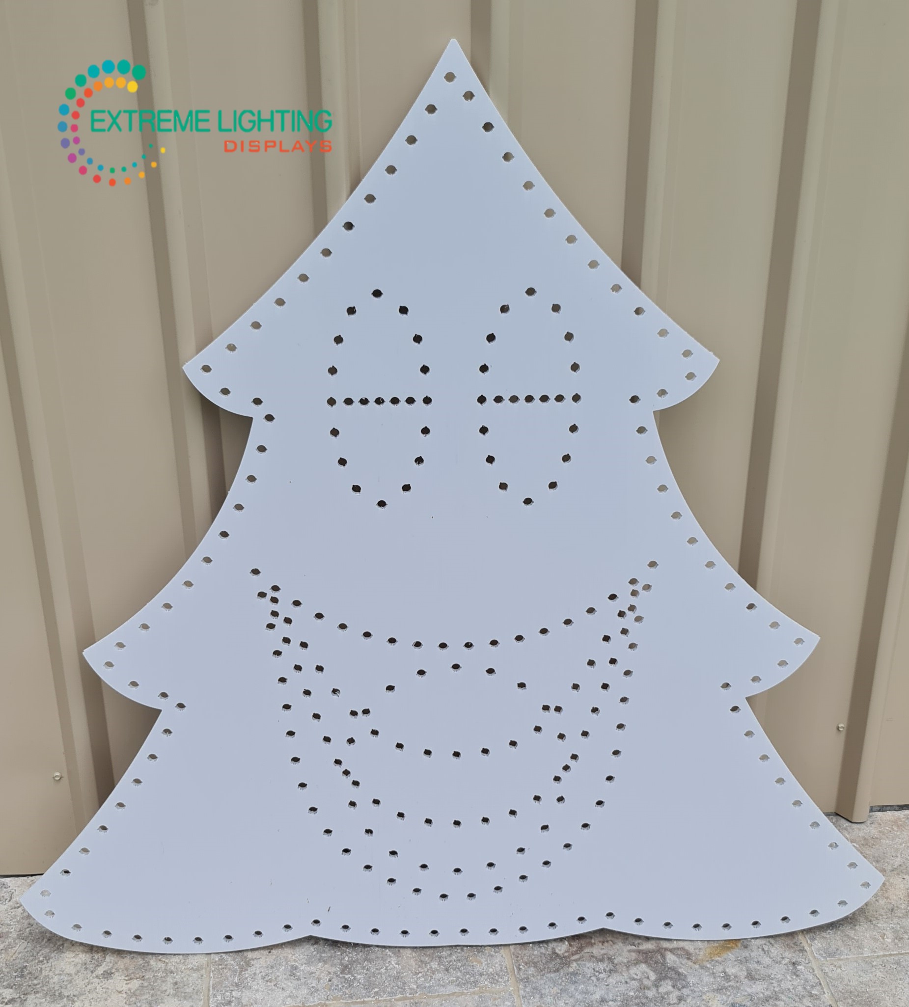
Props have been decided on, and my beautiful wife mentioned that I will be getting some for my birthday, so we’ll see how that goes when we go pick up the order this coming weekend. More photos to come no doubt!
A singing tree prop – image pinched from the ELD website
Power Supplies
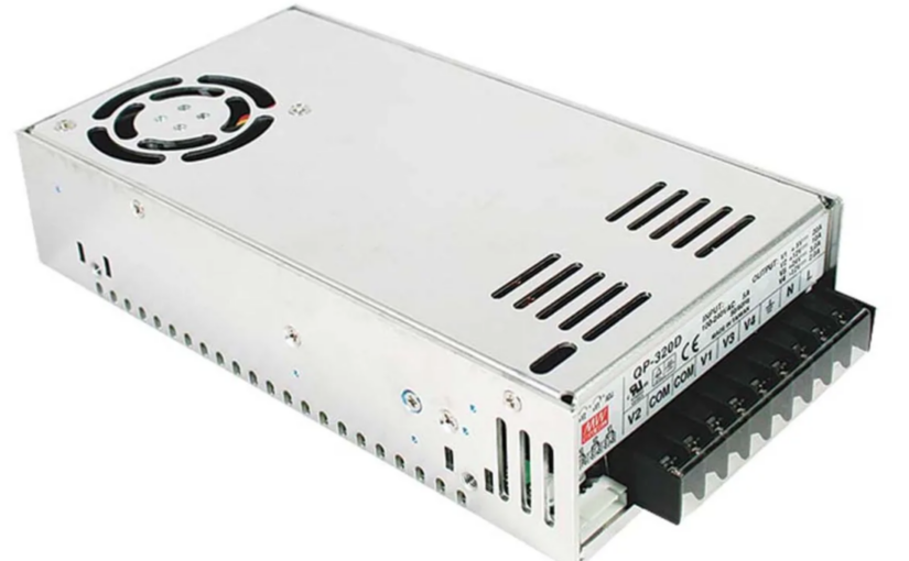
Based on the requirements, I have decided on 3x 24V power supplies (at 480W/20A each), and 16x DC-DC converters scattered around the display. This will mean the bulk of my backbone power (longer runs) can be made with smaller gauge cable, and limit the cabling going all over the place.
Also, I have worked out that due to the much higher pixel density, I’ll need 2x 5V power supplies (at 350W/70A) to run the mega tree and star.
I’ve converted an old small computer power supply which will send out 12V for the floodlights, as these didn’t come in 5V form.
Cabling & Connectors
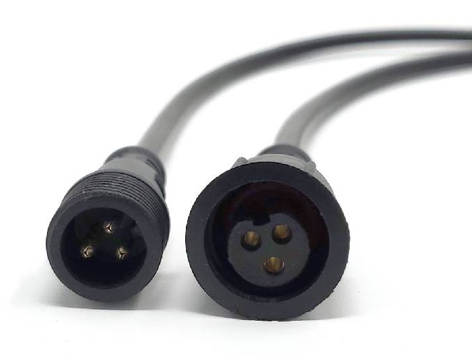
As mentioned above, I have received all the pixel connector pigtails from the Chinese vendor. I’ve decided on using X-Connect plugs and sockets, the biggest reason being is another local display has the same setup, and it means we can help each other out of needed. There is no technical reason to pick each of the plugs over another.
X-Connect Male & Female Connector
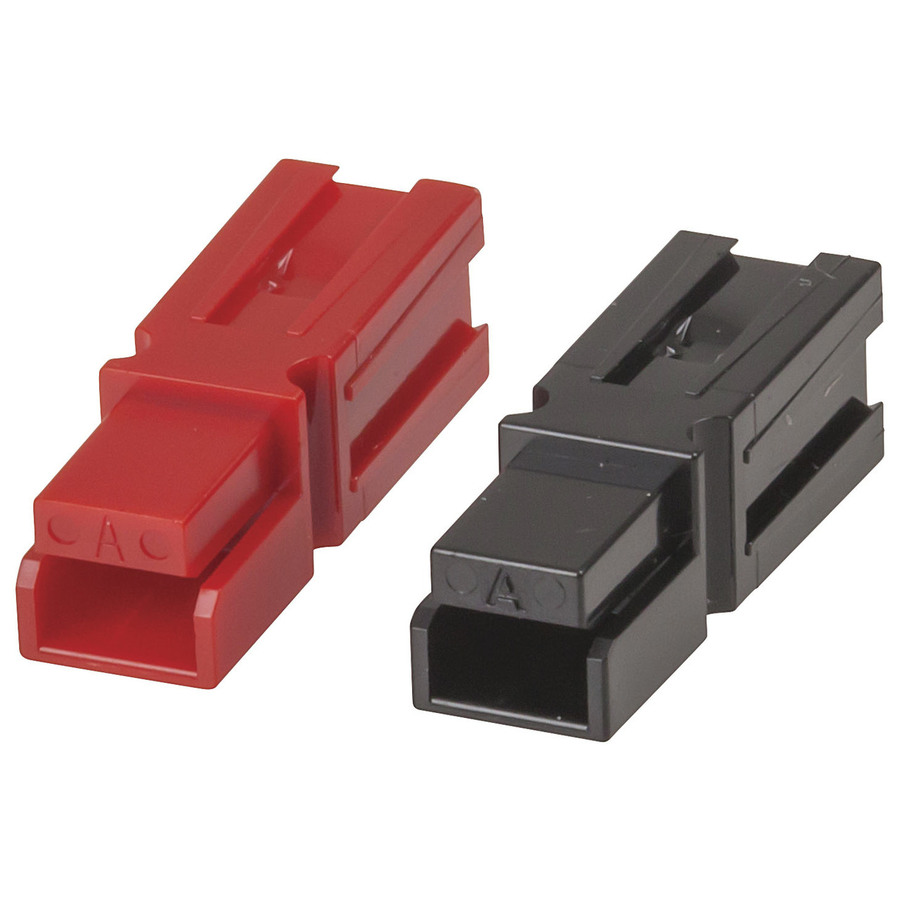
For the backbone 24V DC power, I will use some 1mm2 Bunnings extension cables (with the plugs cut off / replaced) as these can be had for less than $1/metre and have a durable insulation. The connections between these will be Anderson PowerPole, which are genderless connectors, that can handle up to 30A each.
Anderson PowerPole connectors
Once converted down to 5V DC, the power in most circumstances will be delivered direct to the prop using separate power connections. The controller output, whilst being a 3pin X-Connect, will not have any pixel power attached. This is due to my distributed power design, rather than using centralised 5V power supplies.
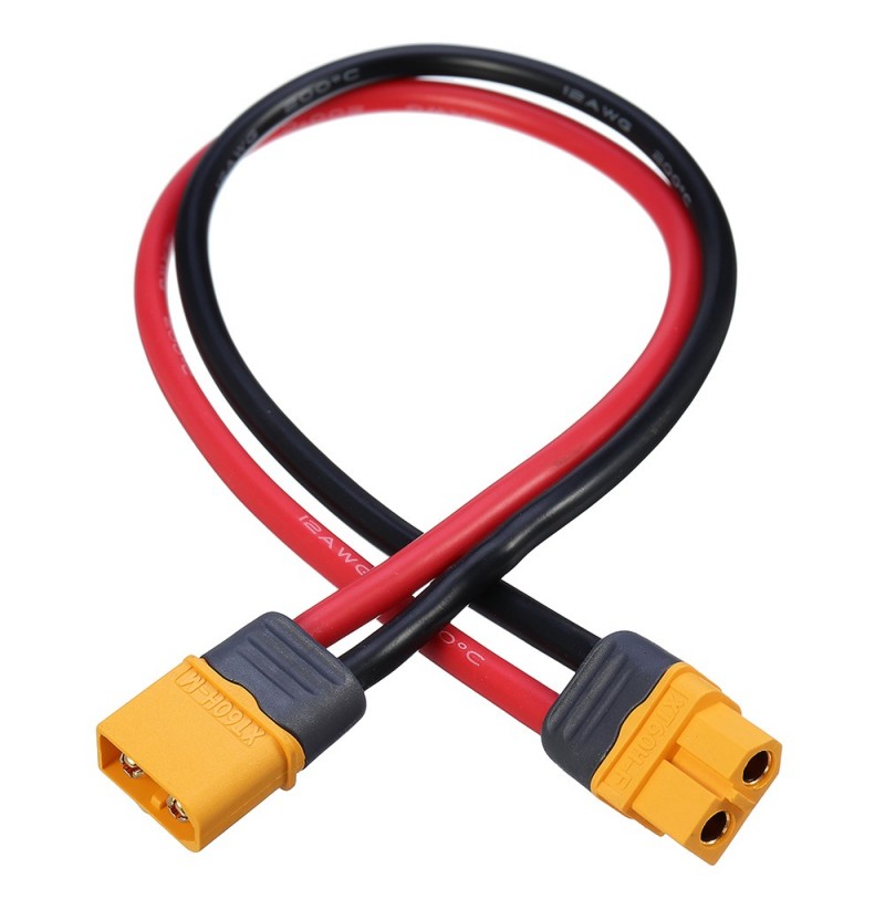
So for this connection, I have ordered some 4mm solar DC cable. It was relatively inexpensive compared to most cable the same size (about half the price), is rated to 120 degrees celsius, and is also UV protected as it’s designed to go on a house roof with solar panels. Perfect for running out in the garden or around the house. The DC connector I’ve decided to use is an Amass XT60H connector, which can handle up to 60A peak load, more than enough for my needs. It’s a hardy connector with polarity protection and decided for low-voltage DC.
XT60H male and female on a cable
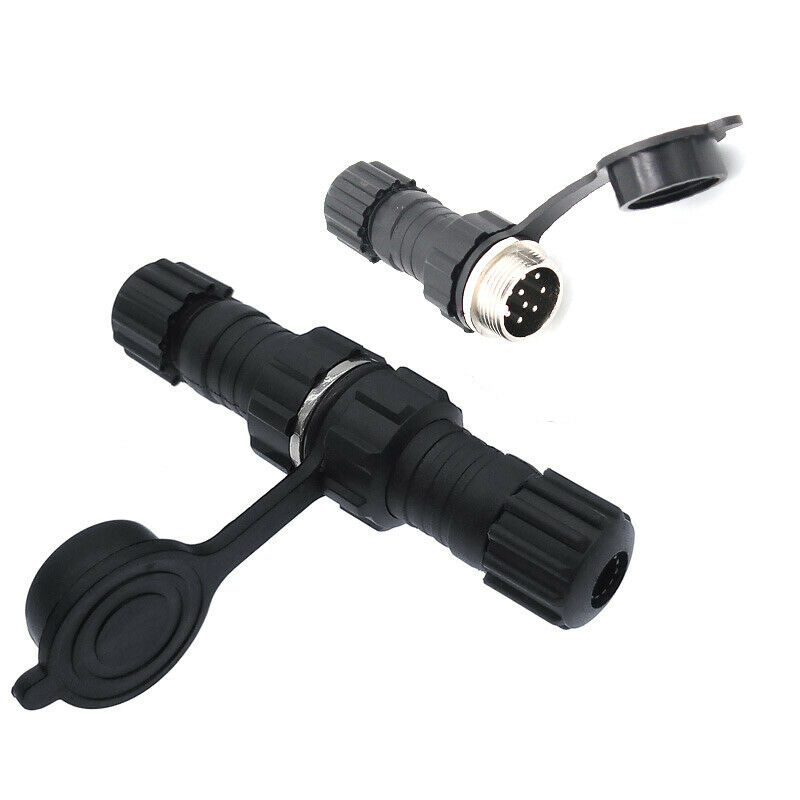
Ethernet will be delivered out to the controllers using CAT6, however from previous projects, I do have outdoor, UV rated, gel-filled kind. I’ve yet to determine the connector I’ll use; based on the water resistant requirement. Right now I’m thinking a round locking 8 pin connector, similar to the below.
Round waterproof connector
Mounting Hardware
This will be loads of experimentation, and making something to fit my particular install. As it stands, I know that I’m going to need loads of conduit for doing the house outlines, I’ll need hundreds of cable ties to hold everything together. There will be many trips to Bunnings as I work out how things are all going to fit together. Sadly the weather in Sydney has been absolutely rubbish in the month of March – places getting flooded (including my back yard, but not to the extreme others have had) – so therefore nothing can be tested and tried.
Conclusions
So as you can see, there is lots to organise, lots to get going. I’m glad I’ve started when I have, given myself all year to plan and build. I’m glad that I’ve already made investments in the pixels, controllers, power supplies and some of the cabling and connectors, as I’ll be able to – and have already done – start getting things built and running.
Many people have helped along the way with design decisions, either by offering assistance, or by writing their experiences on forums such as ACL, where I am immersing myself in their knowledge a few years down the track.
I get excited each time something comes to life; when I see something working, when I feel it all coming together. As I said in the first post, I’m hooked – and loving it!
From my readings, it appears that power distribution is one thing many people struggle to comprehend. There is a fair bit of (basic) mathematics involved, and it requires a certain degree of planning to get right. That said, there are people that will say “XXXXX is the right way to do it”; purely based on their own experiences; and they do not take into account the factors related to a specific installation.
LEDs, individually, do not use that much power. Your typical red LED used as an indicator on your TV, for example, uses around 20mA of current to illuminate, with a turn-on voltage of around 2.1V. This means it’s using about 0.04W of power. This is tiny in the grand scheme of things for a TV, which can draw in excess of 100W. When talking about RGB LEDs, internally, these have 3 modules, one for red, green and blue. By varying the current through these, we can mix many millions of combinations of colours. These use similar currents, around 20mA per LED segment, or 60mA if they were all turned on together (at full white). The driver chip may limit this, however. The WS2811 chip has a driving current of 18.5mA per colour, so 55.5mA for all three segments.
Now, imagine we have 1,000 LEDs. This means we need 1,000 * 55mA = 55 amps of current! At 5V, this would be 275 watts, and at 12V this would be 660 watts. Extrapolating to my expected LED counts of 5,500, that would be a total of 302.5A, or 1,512.5W at 5V or 3,630W at 12V. The latter is the size of my hot water system element!
So why is it higher consumption at 12V than 5V?
Ohms law would state that at a given resistance, the current would be lower if the voltage would be higher. Yes, that’s absolutely true, except that LEDs are not linear. They must be fed by a constant, limited current source. So no matter the input voltage, they will always use the same amount of current. There is a voltage regulator or resistor in 12V pixels, which act as a dropper and dissipate the remaining power. Which essentially means that for my installation, I would be dropping just over 2100W as heat, at full brightness, on full white. Not very efficient at 12V. (Note: Strip LEDs work slightly differently to bullets, and are more efficient, but that’s another story). That’s a typical bar heater! Now – before someone corrects me, yes, I am aware of LED drivers that work differently at a much lower current; which significantly drop the power requirements for 12V (GS8208, I’m looking at you) – the discussion below is all based on a standard WS2811 driver chip.
Which then begs the question, why would you want to use 12V at all?
It comes down to ohms law, in relation to the cabling. An ideal wire is a dead short, it has zero resistance, and can conduct infinite current. Unfortunately, we are not blessed with theoretical components, but we must live in the real world where we have certain physical limitations. Wire comes in different diameters, which is measured by its cross-sectional area, in millimetres squared. Alternatively, the Americans love to use some weird and mathematically useless unit, called American Wire Gauge, or AWG for short.
Now I’m going to get a little maths nerdy here, and there are some certain assumptions/constants about the setup that we’re going to use, to simplify the maths.
The cable from the power supply to the LED string is 15 metres.
On the LED string, we have 600 LED nodes, which at full white, will draw 33 amps
Let’s take typical mains cable that you’d find in the walls of your house. This is usually 2.5mm^2 cable. If it’s made from copper, it has an effective resistance of around 6.9 ohms per kilometre, or 0.0069 ohms per metre. So because we now have our length, resistance, and current we can calculate the voltage drop, using ohms law of V=IR.
Let’s start by working out the total resistance.
Resistance = Length * 2 * Ohms/metre
Why times two? Because our current goes from the power supply, up the length of cable, through the LEDs, and back down the cable to the power supply, so in effect, we have two times the “twin” length of cable to consider.
Voltage Drop = Current * (Length * 2 * Ohms/metre)
Voltage Drop = 33 * 15 * 2 * 0.0069
Voltage Drop = 6.831 Volts!
So if we had a 5V power supply, we wouldn’t have any voltage left at the end of the string. If we had a 12V power supply, we’d have 5.169V at the end. The LEDs might just light, but not quite. As you can see, the drop is linear, and not dependent on the incoming voltage or the voltage of the LEDs. So if we have more volts in and one end, we’ll have more volts out at the other, at the same current.
Let’s reverse the equation. Let’s work out the resistance of cable I need to have a 10% voltage loss on this length of cable, and from there we can find out the size of cable needed.
Ohms Per Metre = Voltage Drop / (Current * Length * 2)

At 12V
	Ohms Per Metre = 1.2 / (33 * 15 * 2)
	Ohms Per Metre = 0.00121 ohms

At 5V
	Ohms Per Metre = 0.5 / (33 * 15 * 2)
	Ohms Per Metre = 0.0005051 ohms
And that would equate to the following size wires- based on a table I found online.
Those are both MASSIVE cables, and not something you want running around your yard. Basically the takeaway from this is that you do not want to push 33 amps over 15metres for a 10% voltage drop.
So how do you reduce the size of the cable? Or is there a better way to do it?
Yes!
Reduce the length of the cable. Based on the above calculation, we can see that the voltage drop is directly proportional to the length of the cable. Halve the length, halve the drop.
Reduce the current running through the cable. Again, it’s directly proportional. Halve the current, halve the voltage drop.
Why not do both?
To satisfy the first, we could move the power supply closer to the LEDs. And to satisfy the second, we could drop the number of LEDs on a cable from the power supply. Rather than one big thick cable, we could spider out multiple smaller cables from the power supply.
More maths Let’s say we put the power supply closer, and we can reduce the length to 3 metres. Let’s also split it up, so we have 200 LEDs on each power cable. We’re going to assume we’re using the same size cable (2.5mm^2 copper).
This then gives us the following formula:
Current = 0.055A per LED * 200 LEDs = 11A total current
Voltage Drop = Current * (Length * 2 * Ohms/metre)
Voltage Drop = 11 * 3 * 2 * 0.0069
Voltage Drop = 0.4554 Volts
At 5V, this leaves us with 4.5446V (9.1% drop), and at 12V leaves us with 11.5446V (4.5% drop). Much better. 15 times less voltage drop. We can run a show with this! Keep in mind, as well, this is on full white, all LEDs, at 100% brightness. If you were to run a show like that, you’d blind your neighbours and no colour is no fun! So not realistic. However; you could theoretically turn on all lights like this. It would mean we need 3 cable runs to drive our 600 LEDs, rather than one, and we’d need to position our power supply correctly. Good practice to do it this way.
Now – I’ll point out that there are a bunch of other things that are not quite accurate to the practicality of it which are not considered in the above calculations. One such example is that it does not take into account that the LEDs are mounted on (cheap thin) wire themselves, which also have their own resistance.
This brings us onto the next discussion point – power injection.
LEDs come on wire which, to be perfectly frank, is inadequate. You can order it with 20AWG or 18AWG cable, but that’s only what’s printed on the side. I prefer to refer to what you purchase with LEDs as CWG – Chinese Wire Gauge. My ‘off-the-cuff’ conversion is AWG = CWG + 4 – so if you see it advertised as 18 gauge, it’s probably closer to 22 gauge (thinner).
So with the currents involved, the further you are away from the power supply, the more voltage drop there is. This could mean that the first LED is getting 100% of the voltage, and by the end of the string, there’s only 50% of the original voltage left. This causes the LEDs to go yellow / orange / red colour, as the Blue and Green LEDs will switch off first.
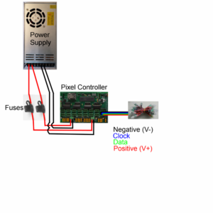
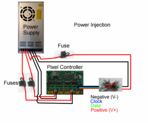
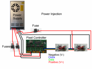
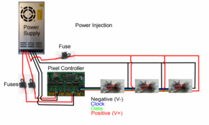
Power injection is connecting power at each end of a string of LEDs, and sometimes in the middle, with a much thicker cable. Here are a few different images that I’ve pinched (from https://www.doityourselfchristmas.com/) that show the methodology.
No Power Injection
Injection at far-end of string
Injection at middle and end of string
Multiple injection points
By running the thicker cable as the injection point, you overcome the resistance of the wire on the pixel string, thereby reducing the voltage drop. This then means the pixels get a more even voltage, and the colour reproduction is more precise.
Putting it all together
So with all this in mind, how am I planning to power my setup? I’m going to be doing a combination of things.
To keep things effficient and not let power go to waste, I plan to use 5 volt pixels all round.
I plan to keep the 5V power supplies close to the props
I plan to power inject every 50-100 pixels, to ensure the pixels all receive decent power.
To satisfy 1) and 2) without running mains wiring everywhere, I plan to use 24V distribution and do at-prop power conversion.
What ho? 24V?
What is this last bit all about? 24V? No one said anything about that. All the talk above is about 5V and 12V!
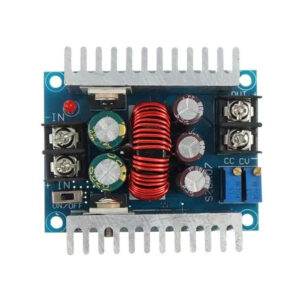
Thinking back to our power calculations above, we can reduce voltage drop by reducing current. Now, whilst 12V pixels are not able to do this due to their design, by implementing DC to DC converters, we can.
DC to DC converter
Power = Voltage * Current Power is consistent across a DC to DC converter (ideally, assuming 100% efficiency).
So mathematically, Power In = Power Out; refactoring and solving for Current Input:
Voltage In x Current In = Voltage Out x Current Out
Current In = (Voltage Out x Current Out) / Voltage In
With 5V pixels and 24V supply, this means that
Current In = 5/24 * Current Out
Current In = 0.208 * Current Out
o we’re straight away reducing our current requirements by 80%. This means the voltage drop on the feeder wires is 20% of what’s required at the props. This is exactly why the power companies give you 240V, but distribute at 11kV, 33kV and 330kV. The current requirements are much lower at high voltage, and so thinner cable can be used (or more end-users for the same size cable).
Coming back to our 600 pixel example above, with 15 metres of 2.5mm^2 cable: The current was 33A at 5V. Translate this to 24V gives us 6.875A. Let’s assume that we’re not completely efficient, and we lose 10% in the converter – so 7.6A to be on the conservative side
Voltage Drop = Current * (Length * 2 * Ohms/metre)
Voltage Drop = 7.6 * 15 * 2 * 0.0069
Voltage Drop = 1.5732 Volts = 6.55% total drop
This leaves us with 22.4268V at the far end. Heaps for the DC to DC convertor to work with!
The DC to DC convertors are also alot more tolerant of voltage drop. If they are set to put out 5V, they will keep doing so, as long as the incoming voltage is over 8V. In other words could lose 66% of the incoming voltage before they cut out. Note that this isn’t an excuse to just run super thin wire everywhere, it needs careful planning too, but it does end up being a cost saving in the wire, as well as being easier to work with.
I’ve yet to draw up the full diagram, but so far all the calculations for this method of working means that I will be running pretty efficiently, and will be able to light up to any setting I wish, without fear my power requirements aren’t up to scratch. Once I get everything designed, I’ll put together another post detailing all the connections, wire lengths, measured resistances, voltage drop measurements (real life vs theoretical) etc.
Today’s post I’ll be answering the above question in very broad sense. What do I mean by this? Well, the question can be interpreted in a few ways, whether it relates to software, hardware, electronics, etc. So I will break down the various components of the system at a high level.
The exact hardware technology choices – will be up and coming in Decision #6 down the track – or have been discussed before in Decision #2.
We want to take some form of programming, and make lights blink to our instruction – so what comprises a Christmas Light system from end to end, in order to make that happen? Let’s start at the fun bit, the blinking lights, and work our way back to the source.
LED Pixel Lights
These are so called because they operate similarly to a pixel in a computer monitor. They have three coloured LEDs, red, green and blue, which when turned on to varying brightness can mix and create the full spectrum of colour. In Decision #2, I discussed the different physical types of pixels used, but not their operation. Pixels are controlled by an Integrated Circuit, which takes in some format digital signal, and reads the red-green-blue (RGB) data from the data to switch on the three elements at an appropriate brightness. There are a numerous formats, but the most common is WS2811, discussed below.
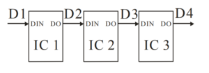
The lights are daisy chained, and the first light is fed all the data for the entire string of LEDs. Every pixel chip grabs the first pixel worth of data from the stream, processes it and illuminates. It then strips that data from the stream, and passes on the remaining data. Because of this, there are no ‘addresses’ – each pixel just processes data in order. If pixels for a certain function are swapped, then the data stream needs to have the data swapped too.
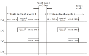
The below diagram shows how the pixels are interlinked, each pixel has a data input (DIN) and data output (DO). They are connected serially. The second image shows the data at the 4 points between the interconnected pixels, where each is stripping the first data it sees and passing the rest down the line.
Interconnection between pixels
Data as it travels between pixels
Pixel Controllers
In order to generate the pixel data, we need a controller that understands the protocol used by our pixels. There are numerous controllers out there on the market, many developed for the Christmas Lighting hobby, and some professional designs as well.
These controllers will generally receive channel-based data in a standardised format over an ethernet network – typically E1.31 (sACN / DMX over IP) and decode this into RGB pixel format from triplets of channels. There are other protocols, such as ArtNet and DDP, which perform a very similar function to E1.31, but with minor protocol differences.
You can map the input data to the output pixels, as well as set global brightness levels, set up virtual strings, and set the pixel output formats.
Some controllers are stand-alone, meaning they run firmware in them, and operate as a complete unit, and some are expansions on top of Raspberry Pi or BeagleBone boards, utilising the GPIO connections and programmability of these platforms.
Controllers range from 1 to 48 pixel outputs, with anywhere up to 1500 pixels per output, as well as being able to drive differential outputs which allow long-range transmission of pixel data without signal quality loss.
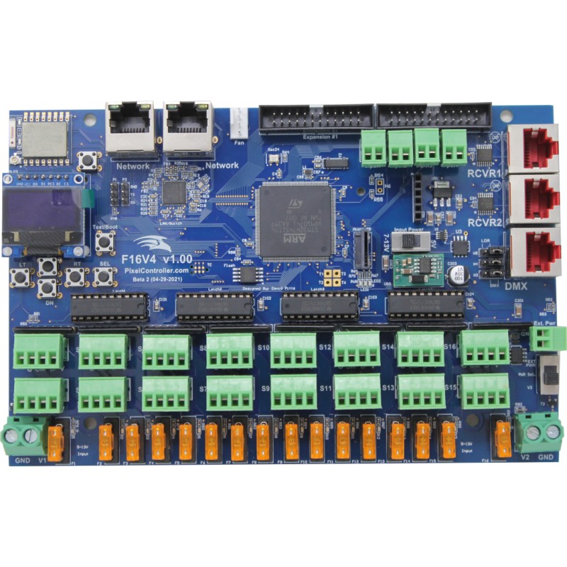
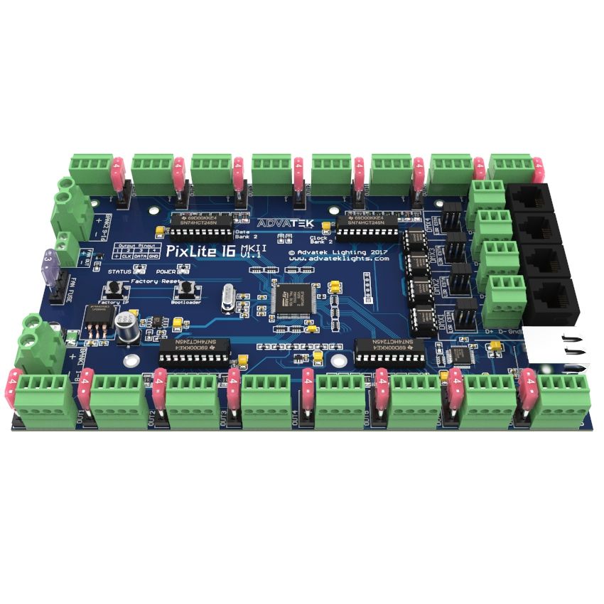
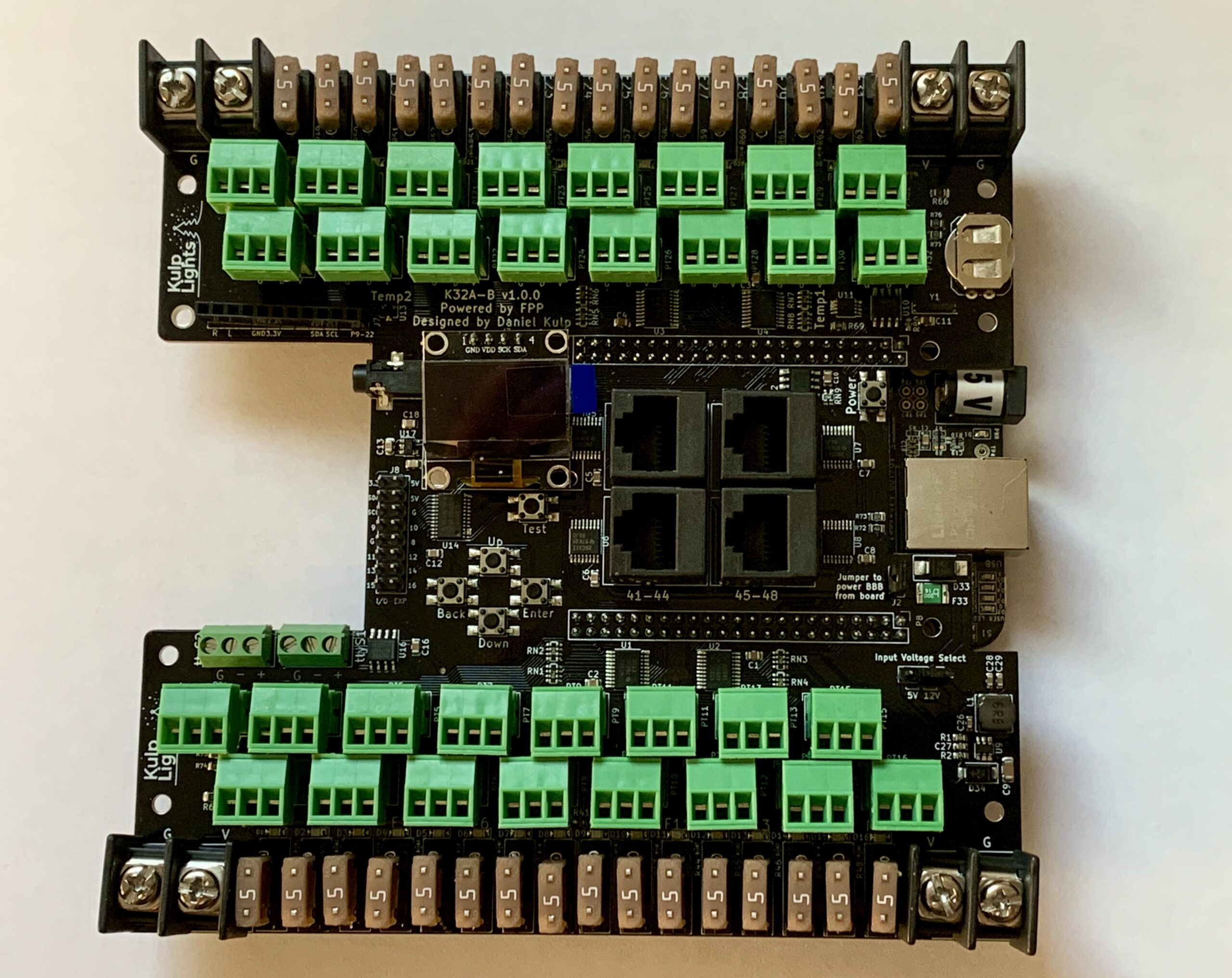
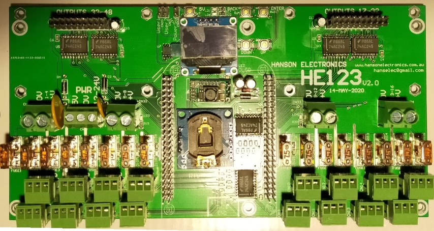
Four examples are below, two firmware boards – the Falcon F16V4, Advatek Pixlite 16 mk2 – and two BeagleBone boards – the Kulp K32a-b and Hanson HE123mk2. Click the images to go to the manufacturer website to find out more.
Once a sequence has been programmed, there needs to be a way to generate the control data – Artnet, DDP or E1.31, and send this to the pixel controllers, for display on the lights.
This is where a playback platform is needed. There are three main ways to do this; 1. Use the controllers inbuilt player, if it has one, 2. use a PC running software, or 3. use a small-board computer running software.
When using the controllers player, the sequence is uploaded to the device, which generally controls its own outputs only. The controller would also need to support generating the sound, if your sequence is programmed to music. Currently the Falcon controllers are the ones best suited to this mode of operation.
On a PC, software called xSchedule can generate the required network output from the sequence files. The PC sound card can also generate the audio. xSchedule can run on Windows or Linux, so there is a choice of operation there. The disadvantage to this is that it requires your computer to be dedicated to the show, meaning you can’t use it for other purposes (well, you can, but it could cause show issues) – and the power consumption of a full-sized PC is not immaterial.
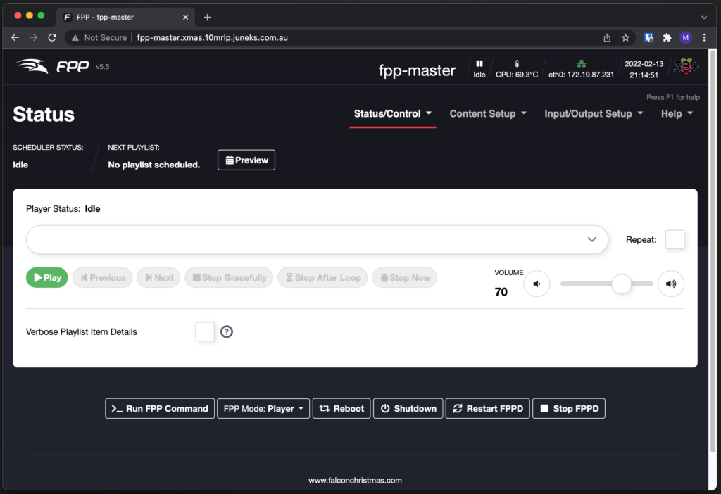
The third option is using a small-board PC, such as Raspberry Pi. A piece of software called “Falcon Player”, or FPP for short, was developed for this purpose. It is flexible enough to play audio (either via USB sound card or the boards sound output) – as well as control pixels via ethernet output, and local connections. It can also receive data from another player, or perform synchronisation of local playback to minimise network traffic. In fact, the small-board computer based controllers (such as the Kulp and Hanson above) use FPP as their software loaded on their computer.
This is a screenshot of what FPP looks like without anything loaded. It uses a web front end that’s straight-forward and easy to use.
Falcon Player running on a test machine that I’ve set up
Sequencing
Creating a sequence involves loading in your music track, configuring what your display looks like, and placing effects as you see fit. You can also import sequences that others have created (there are numerous vendors that sell sequences). Three main packages are used within the hobby – those are xLights, Vixen 3 and Light-O-Rama.
The first two are open-source / free, and the third is a paid product, specifically designed to work with the Light-O-Rama software.
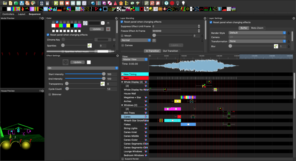
When looking at the pieces of software, I found xLights to be the most intuitive, and it has a massive community support group behind it, and loads of online videos. It also integrates well with the controller hardware, allowing remote configuration directly from the software.
xLights will run on Windows, MacOS and Linux, with cross-compatibility of files between all the platforms. Additionally, it can import files from other platforms and work as a go-between if needed.
xLights running on MacOS
Network
Being a network engineer, dealing with real-time traffic such as voice, I cringe a little bit at some information that’s posted out there. Plenty of information will state that you should have a dedicated network, separate from your home network. This, I agree with 100%. This complicates things as your sequencing computer needs access to both networks to operate, which can be achieved a couple of different ways. This is where I think some of the suggestions are a little wild, but for the layman they might work well. But, I won’t get into the ins-and-outs of it here, suffice it to say, that I have read the advice with a grain of salt, and come up with my own network design.
My home network is not your standard home network. I run a bunch of enterprise network gear (Juniper, Cisco, Huawei, Mikrotik), have a few servers for virtual machines, development environments, and as well I host mail and files for the family business. As such, there are around 12 VLANs split across as many subnets, and dynamic routing linking my property to 5 others.
So I have added another VLAN, logically segregated from the rest of my environment, and there will be a dedicated switch running the show when it happens. The advantage of configuring it this way is that it gives me the flexibility to incorporate the subnet into my standardised networking, that IP routing ‘just works’, and that I can light up a show-network port anywhere on my network, such as in my workshop as required.
Power
This is something that deserves a whole new post. Coming up next! 😉
Summary
So as you can see, plenty of pieces of hardware and software tie together, sitting on an underlying network, making all of this possible. I’m sure this all makes sense in my mind, and if anyone is reading this planning their own show, I hope it makes sense to you too. If you are starting a show for yourself, please, feel free to reach out to me with any questions or comments; I’d love to help; alternatively (and maybe as well as!) – sign up to AusChristmasLighting – there are some fantastic resources in there and plenty of folk who have done this many times before.